
Design basis
Risk assessment and LPS design under IS/IEC 62305

Lightning protection
Conventional lightning protection designed around IS/IEC 62305, with roof conductors, air terminals, bonding, down paths and earthing.
Request a specification reviewDirect answer
Conventional lightning protection uses air terminals and a planned conductor network to intercept a strike and carry current to earth.
3E supports layouts based on IS/IEC 62305. The approved roof scheme may use 25 x 3 mm GI strip or 8 mm aluminium conductor along the parapet, with down paths, bonding and earth termination drawn together.
Risk assessment and LPS design under IS/IEC 62305
25 x 3 mm GI strip or 8 mm aluminium conductor where approved
Franklin rods, mesh or rolling-sphere arrangement as the design requires
Technical view

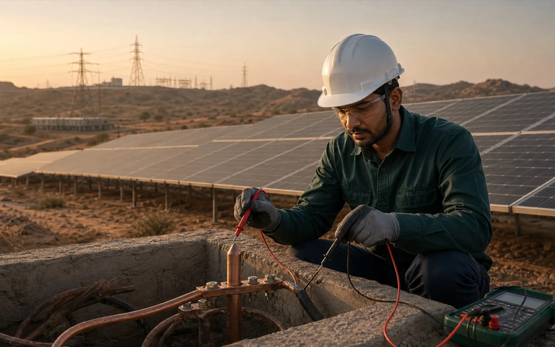
Survey the real roof. Parapets, tanks, solar arrays, plant, access routes and nearby structures alter the interception and conductor layout, so a generic rectangle rarely survives contact with the building.
Lightning current dislikes detours. Sharp bends, long loops, hidden joints and poor bonding can spoil the planned path, which is why routes need coordination before facade and civil work close them.
Specification
The conductor examples are documented options, not universal sizes for every structure. Risk and layout calculations remain project-specific.
Applications
Use the application to settle the duty, material, dimensions and evidence required in the offer.
Roof networks shaped around plant, services, access and the assessed protection level.
Air termination and conductor routes coordinated with arrays, inverter areas and earth networks.
Parapet and roof layouts integrated with bonding and surge coordination.
Questions from site and procurement teams
Not by assumption. Air-terminal count and position follow the risk assessment, roof geometry and selected design method.
No. Both are documented roof-conductor options, but the approved design, joints, exposure and metal interfaces control the final choice.
The earth arrangement follows the complete design. It must be coordinated with bonding, spacing, test points and the site's existing earth network.
Bring us the drawing
Send roof levels, exposed equipment, building use, conductor preference and existing earthing. We will begin with the risk and route, not a rod count.
Send the requirement on WhatsApp